Energy Savings of 55%
09/22/2025
The new cooling system provides dramatic improvements in performance and efficiency.
A plastic bottle plant manufacturer in Southern California needed to renovate the process cooling systems for a blow-molding facility. As is typical for this type of plant, there were separate chilled water systems to provide bottle machine process cooling distinct from manufacturing space humidity control due to the significantly different characteristics of the two applications. One factor driving the renovation was the need to add more humidity control. The existing system was not keeping up and conditions in the plant were unsatisfactory.
Given the two-system design, the standard approach would be to add a chiller, pumps, piping and production room air handler. These would be added incrementally to the existing humidity control system or set up as a standalone system. Unfortunately, several inescapable disadvantages would be compounded by adding more equipment to the two current systems.
Having separate systems to meet these distinctly different requirements mandates significant capital investment for the duplication. Each system has its own chillers, pumps, and support equipment, including makeup systems and water treatment, which was taxing the space-constrained site. Maintaining the separate systems means there are multiple, minimally supported sets of equipment that were more or less ignored as long as they were running. The overall efficiency of the systems was low due to the challenging operating characteristics of the machine cooling system and the seasonally off-design loading of the humidity control system.
An innovative approach successfully combined both requirements into a single, high-performance system that provides improved cooling to the plant with reduced investment and at significantly lower operating costs.
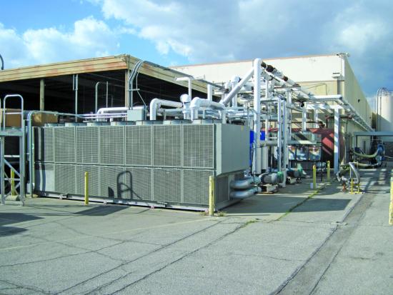
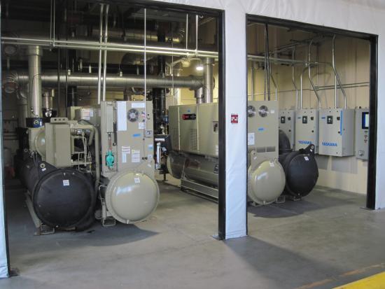
The legacy cooling systems included complicated piping.
Two Cooling Systems with Two Sets of Requirements
The two cooling applications have nearly opposite features. The humidity control system is intended to keep the room air dry enough to minimize moisture condensation on the bottle molds, while the mold cooling system removes heat from the material forming the bottles. Like a cold beverage container, the molds sweat if their surface temperature drops below the room air dew point. Any droplets hurt product quality.
The humidity control system is essentially conventional air conditioning with standard mid-40°F (around 7°C) chilled water (CHW) supply temperatures combined with air handling units (AHUs) optimized to remove moisture. The AHUs require moderate cooling water flow and pressure requirements of around 2½ gallons per minute (gpm) per ton and 12 psi differential at the AHUs. When functioning properly, the total AHU CHW flow varies with the actual dehumidification load. Seasonal and daily variations are typical as the AHUs operate to keep the dew point below a setpoint target.
The machine cooling system requires moderately warmer CHW, typically from the high 40s to the low 50s°F (8°C-12°C), with a higher pressure requirement for the bottle molds. Ideally, the flow through the molds is high to maintain uniform temperatures, resulting in relatively little water temperature change from inlet to outlet. This application requires 5-6 gpm per ton and 40-50 psig (2.8-3.4 barg) differential. The total cooling load varies with the number of machines running, the specific mold requirements and the material being run. While these vary with production requirements, there is little seasonal change driving the variations.
A Fluctuating Relationship Between Humidity Control and Mold Cooling
Given the distinct characteristics of the load types, the humidity control system could be a higher or lower load than the machine cooling system depending on the time of year and the machine operations. One observation from the initial system review was that part of the mold cooling system supply temperature variation was compensation for the ineffectiveness of the humidity control.
At times when the humidity control system underperformed, the mold temperature was raised to reduce droplet formation. This, in turn, hurt the plant’s throughput, as cooler molds can run slightly faster cycles. In a real sense, the plant had to reduce production due to the limitations of the cooling systems. Not only did the plant have to forgo greater output, but it also had to constantly adjust the cooling systems to get the most out of them as conditions changed. This taxed the operations and maintenance staff as they tweaked the temperatures up and down over the seasons and sometimes even through the day, trying to get the optimum balance of mold temperature and ambient humidity.
A Default Plan to Add a New Chiller and Air Handler
Given these cooling system issues, the corporate engineering and plant management team decided to explore its options. These ranged from adding incremental equipment to replacing both cooling systems under the presumption that new equipment would improve plant conditions. At this point, the plant involved ISG in the analysis. The default plan was to add a new chiller and air handler. This approach required more space, however, which was challenging given the location.
The existing cooling systems had two 225-ton air-cooled process cooling chillers and one 200-ton air-cooled chiller dedicated to the AHU system, with separate pumping and piping for each system. The process cooling system had hot well and cold well tanks with a recirculation loop to the chillers and a separately pumped loop to the machine load. The AHU cooling system was a closed-loop system with dedicated pumps. The planned humidity control modification would add at least another chiller and pumps.
The maintenance staff manually turned the constant speed pumps on and off as they deemed necessary. The result was that both loops into the plant saw significant pressure variations as the number of pumps and the number of lines running changed, and as the AHU cooling control valves thermostatically adjusted. Typically, seven or eight of the 10 installed pumps ran at any given time.
Analyzing Flows, Temperatures, Pressures and Power Logging
The company had worked with ISG before on cooling system performance improvements and requested help selecting replacement cooling equipment. It needed to know the size and type of chillers that should be used, and whether or not pumping or piping changes would improve the performance of the new chillers. To answer these queries, ISG performed a design analysis and an operating data survey with detailed field measurements (including flows, temperatures, pressures and power logging). The results served as the basis for evaluating potential options.
After evaluating the current and projected design loads and conditions, ISG proposed creating a combined cooling system. The plant was willing to consider this approach as long as the firm also analyzed other, more conventional options.
The plant was doubtful a single system could meet its two separate cooling requirements, and concerned that if the installation didn’t function as planned, production would suffer. However, it ultimately accepted the idea that a combined cooling system could meet the total cooling requirements with less capital investment while providing reduced maintenance requirements, a smaller total footprint and greatly improved efficiency. Lower energy costs were important, as the California plant is in an area with high energy rates.
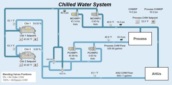
A combined cooling system schematic from the controls display shows how the system operates. Click to enlarge.
Adding Two 400-ton Water-Cooled Chillers
The firm’s combined cooling system recommendation consisted of two larger water-cooled chillers served by a single cooling tower. The 400-ton chillers were sized so they provided essentially N+1 redundancy when the plant operates at normal loads. In addition to the chiller change, this design eliminated the tanks and recirculation loop in the process cooling system. Instead, it offered a single closed-loop system with separate branches to meet the distinct cooling requirements of the AHUs and the molding machine.
The separate branches have independent pumps selected specifically to meet the two applications’ different pressure and flow requirements. The piping design has the main CHW pumps providing circulation to the total CHW flow. This is followed by the process pumps only pumping to the machines at the higher pressure required for their cooling. With the improved design, there are only six pumps in the system, and normal operations only require three to be running. This is reduced from 10 pumps total and six pumps running before.
The critical characteristic of the combined cooling system is the use of three-way valves in the water supply to the process cooling pumps. These three-way valves (there are two in parallel operating in an overlapping manner) enable the process cooling pumps to flow chilled water that can be either 100% chiller-cooled water, 100% return CHW (blended AHU and process cooling coming back from the plant) or anything in between. The three-way valve control is critical, as it provides the higher process cooling supply temperature needed to avoid mold condensation. The process supply temperature can be as warm as the blended return, so practically speaking it is limited to around 8-10°F (4-6°C) warmer than the AHU supply temp.
The last component of the combined cooling system plan was several changes to the piping system that, in combination with improvements in the pumping control, provide more uniform cooling throughout the plant. These include adding an intertie pipe that connects the two process cooling branches (somewhat like adding a loop pipe in a compressed air system), as well as moderately oversizing some of the added piping for minimal pressure drop in the distribution system.
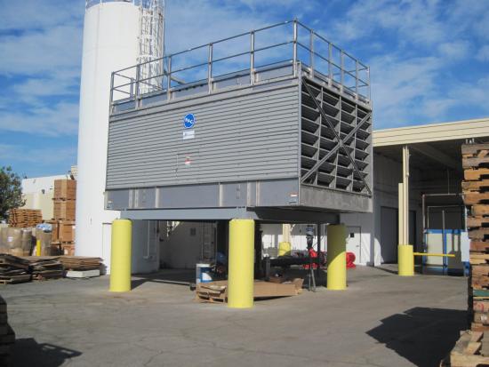
The cooling tower and pumps for the combined cooling system.
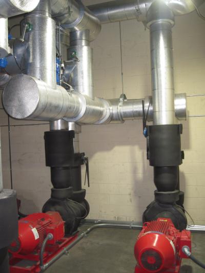
Three-way valves and dedicated pumps enable the combined cooling system to meet distinct cooling criteria.
Combined Use Chillers Save on Energy Costs
The combined cooling system installation is now complete, and provides the plant with many advantages including the following:
- Dramatically improves process cooling conditions: more stable temperature and pressure supply to the production machinery, as well as more uniformity across the plant, virtually eliminating issues with mold condensation and other inadequate cooling conditions.
- Significantly reduced maintenance costs: improved operating conditions for the new equipment (which is variable in response to needs, and no longer in constant use at full speed) with automatic rotation between components for consistent use.
- Improved water conditions with closed system operation: removing open tanks enables air removal and better anti-corrosion treatment standards, and also saves the space formerly required for tanks.
- Major reduction in energy use: improved loading of chillers from combined uses (higher delta T across evaporators), conversion to higher efficiency water-cooled chillers, high-efficiency pumping and piping design (pump selections, reverse return and low-loss system piping features), elimination of constant-flow chiller recirculation loop and dynamic control of the cooling system according to actual production and AHU requirements.
- Lower staff support requirements: much less required daily maintenance team activity, simple one-switch system starts and stops, fewer components to support, fault handling to defer most equipment issues to day shift maintenance availability.
- Reduced space requirements: while the original chillers and pumps were outside, the plant site is space-constrained; the revised cooling system uses less space than the original system with the required AHU expansion would have needed.
The combined cooling system design was sufficiently beneficial that the plant worked with ISG to recreate it in a new construction project that followed 18 months later.
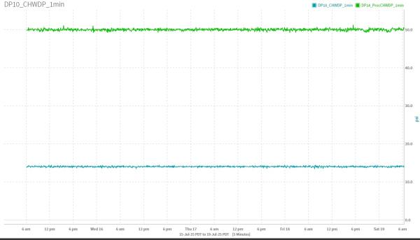
As this graph shows, differential pressures are nearly flat in the combined cooling system. Click to enlarge.

Temperature stability is dramatically improved, typically under +/- 1°F (0.6°C) variation. Click to enlarge.
Energy Savings of 55%
In the several years since the project was completed, the combined cooling system has provided dramatically improved operations for the plant. The cooling water temperatures and pressures have less than 10% of the typical variation of the previous systems. The improved conditions have led the plant to install additional bottle molding lines, with the additional sales volume delivering a significantly greater return than simply the energy cost savings.
Energy savings are around 55%, which is extraordinary for a cooling system that relies on mechanical cooling year-round (the location does not support free cooling, as winter is not cool enough to justify the investment). This has been particularly beneficial for the plant as its energy costs have increased by over 50% since the project was approved. As a result of this project, the plant saves over $270,000 per year on energy costs.
As noted, the client has used the combined cooling system design on a new project. While the wholesale replacement approach is too costly for some existing system renovations, many of the specific concepts have been applied as improvements to other systems. These include differential pressure control and (where applicable) cooling tower operation optimization, in particular resetting the set point based on the wet bulb temperature and managing the tower water flow based on actual temperature.
The project team learned several lessons in implementing and starting the revised system. One key insight was to train the maintenance staff on the different requirements of the new system, as the addition of a cooling tower was new to the plant. Somewhat unique to the location, which is temperate and typically has low precipitation, keeping the equipment protected from weather during rare but intense storms was a hard-learned lesson. The previous systems were installed outdoors and were unaffected by rain. The new system, with variable frequency drives and standard NEMA 12 rating control enclosures, had several instances where the dock-style roof leaked, necessitating various temporary and now permanent fixes.
Summary
Faced with the requirement for improved cooling, a blow molding plant chose to invest in a significant redesign of its cooling systems that combined two separate systems into a single, integrated system. The combined design leveraged the components to provide a more controlled, efficient system while also requiring less space than the alternative would have needed. The new system has demonstrated significant benefits and will perform for many years to come.
About the Author

Clayton Penhallegon, Jr. is the Managing Member of Integrated Services Group, which specializes in industrial cooling water system operational effectiveness and cost reduction. He has worked for over 35 years with various industries, including plastics, paper, wood products, metal containers and textiles. He holds a Bachelor of Mechanical Engineering from Georgia Tech, an MBA from Georgia State University and is a registered PE in Georgia.
About Integrated Services Group
Integrated Services Group performs industrial cooling water system operational effectiveness and cost reduction technical services. Its services include system assessments, new and upgrade system design, system start-up and retro-commissioning and high-efficiency control design and implementation. ISG celebrated its 25th anniversary in 2022 and serves clients throughout North America. For information, visit https://www.isg-energy.com.
For similar articles on Cooling Controls System Assessments, please visit coolingbestpractices.com/system-assessments/cooling-controls.
Visit our Webinar Archives to listen to expert presentations on Cooling Controls System Assessments at coolingbestpractices.com/magazine/webinars.