Advanced Centrifugal Chiller Technology, Variable Speed Drives and Heat Pump Integration Improve Lift Management and Energy Performance
Working with higher chiller lift can be a cost-effective method of driving heat recovery solutions or a result of the need to evacuate heat at higher temperatures with less water. We spoke Rob Tanner, Marketing Director, Applied Equipment, Johnson Controls, about ways engineers can optimize chiller lift and the technology pushing the area forward.

Rob Tanner, Marketing Director, Applied Equipment, Johnson Controls.
Understanding Centrifugal Chiller Lift
Best Practices: How would you define chiller lift qualitatively?
Rob Tanner: It’s easier for people to think about chiller lift in terms of temperature rather than pressure. They’re correlated: Both go up when the temperature goes up, and both go down when the temperature goes down. Chiller lift is the temperature difference between the condenser outlet and the leaving evaporator outlet. Think about lift as water temperature you get on the condenser side – the useful water temperature for heating – and water temperature you get on the evaporator side – the useful cooling temperature – particularly in applications where you’re going to use both of those.
The pressure relation shows as you go to higher condenser temperatures, you need a chiller able to deliver at higher pressures. It comes down to your refrigerant compressor’s capability to deliver pressure, with that particular refrigerant, to achieve the condensing temperature. The next question is how do I build a chiller able to handle that pressure? Let’s say a comfort cooling chiller’s pressures will be 150 psi or less, but I’m going to get into 300 psi-plus pressures when I start using it for high temperatures, like in a heat pump application.
I could specify a refrigerant pressure in the evaporator and a refrigerant pressure in the condenser. The difference between the two is pressure lift. Pressure lift is defined by how much pressure is added by the refrigerant compressor. The purpose of the refrigerant compressor, centrifugal or positive displacement, is to raise the pressure of the refrigerant gas. It’s the water temperature that connects most with people, but you can talk about both terms.
Best Practices: Let’s get into low, medium and high lift. How can we define each of those?
Rob Tanner: 70°F (39°C) of lift or less is a low lift application, and I can take advantage of the efficiencies available there. The less lift I need to accomplish, the less my refrigerant compressor has to work. There are lots of applications where low lift fits the requirement. A lot of comfort cooling applications fit low lift, and it’s common in any commercial building where we’re going to deliver chilled water temperature somewhere in the mid 40°s F (around 7°C) to be able to provide cooling or heat removal.
The middle road says, if you can get high lift, you can do anything you need to do, but is it optimal? Let’s say I need around 100°F (44°C) of lift. I could use a product designed to achieve high lift, but at what cost? I’m now not right-sized for what I need. It’s much more than I need. There’s a middle ground. I have product solutions where I can have something in between and optimize around that lift. Maybe I only need 140°F (60°C) water. I can do a lot of useful work with that.
High lift is usually driven by a need to either reject heat at a much higher temperature because I’m not using a cooling tower or the climate doesn’t allow for low entering condenser water temperatures. Say I’m in the Middle East and ambient temperatures are hot. In order to reject heat, I’ve got to be warmer than that. I’ll need a higher lift to overcome heat rejection. I may not deliver any lower temperature, but I need higher lift to be able to reject heat.
Any place you need higher temperature water, higher lift helps you achieve it. You could still be at the same evaporator temperatures. High lift applications can go pretty high depending on the refrigerant compressor technology.
Changes to Achieve Optimal Chiller Lift
Best Practices: If I see my lift is dropping or rising, how can I diagnose the system? What changes can I make to reset it to an optimal state?
Rob Tanner: If I have a scenario where I’m over-lifting, that’s going to represent itself pretty clearly in power draw on the refrigerant compressor. We’re increasing the pressure gap between the inlet and outlet of the refrigerant compressor and the temperature of the evaporating and condensing process. The gap in the temperature grows. I think you’d look at it and say, "I’m consuming additional power, so I’m going to see pressures and temperatures change."
Then, it’s a question of saying, "What’s creating that draw?" If it’s a cooling-only application, my control point is my chilled water temperature. If I’m able to maintain that, but I have a higher lift, I’d start looking on the heat rejection side and ask, "Is something happening there that’s telling the refrigerant compressor it’s not able to achieve this without overcoming more heat rejection? Is there something happening in the heat exchange process?" It could be in the chiller bundle itself or in the cooling tower.
Usually, it goes the other way, where you have less ability to transfer. Heat exchangers degrade because they’re fouling or they’re not able to transfer heat as well. That could be an indication overdrive is trying to compensate for heat exchange. In that case, we don’t have good heat transfer in some part of that heat rejection system.
On the low end, the question is more often, “What’s going on with the refrigerant compressor?” If I’m not achieving the lift I expect, where am I losing? Have I lost capability? Has something happened to the impeller? Did the impeller break? Is it spinning as it should? Have I lost coupling and connection to the motor? The tendency is to ask, “Is what’s happening in the refrigerant compressor circuit?” It may not be the refrigerant compressor itself, but it would be some subsystem of the refrigerant compressor diminishing its capacity to lift it to the level it needs. We’re not seeing the load on the evaporator side, so we’re not going to raise it as much. Those are a couple of first indicators to look at.
When the power draw on a refrigerant compressor is too great, the first step is understanding what’s causing that draw.
A Growing Need for Higher Lift Solutions
Best Practices: Why are users demanding higher lift solutions? Heat-intensive processes have long been around.
Rob Tanner: It’s the desire to say, “I want to keep the heat from a cooling process. I’ve got a need for both: I need to cool something and I need to heat something. I’ve got that demand consistently and predictably, so I could right-size a solution and go higher.” One of the things driving the trend for higher lift is a growing demand from industries unable to get enough cooling tower water for heat rejection.
The numbers are so big that no municipality is going to let you have that much water. You’ve got to have a way to reject heat without the benefit of the evaporative process or with some reduced capability. Now, I’ve got to overcome higher condensing temperatures. I need more lift to achieve that. I can’t just shift that lift and say, "Oh, let’s deliver warmer water and try to make that correlate directly.” I need to still do what I’m doing on the evaporator side, but my condenser needs to be able to reject at a higher temperature. Increasingly, we see air-cooled and water-cooled products doing it. If I’m rejecting heat without using evaporative water, I’ve got to have a higher condensing temperature. That’s a big and growing driver for higher lift.
The other factor is heat that might normally be thrown away. It feels like it’s relatively low quality, but it might still be 100°F (38°C). I want to turn that into something useful. I might say, "Rather than reject it at 100°F (38°C), could I go through a process where I could get that to 140°F (60°C), 150°F (66°C), maybe all the way up to 180°F (82°C) or above?" Now, I can use it to replace something that might normally burn fossil fuels. It’s more cost-effective to use that solution to get the heating I need rather than firing the boiler. It drives people to solutions delivering a higher lift.
Chiller Control Methods for Energy Efficiency
Best Practices: How does modern chiller technology use lift considerations to deploy control methods for energy efficiency? What are some of the methods we’re capable of?
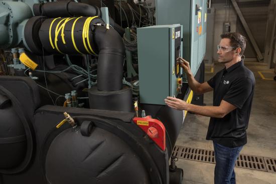
Rob Tanner: With a refrigerant compressor and most modern systems today – unless you’re base-loading a product because it’s going to run full out all the time – you’re going to vary the capacity of the chiller with a variable speed drive. You’re going to take the efficiencies you gain in slowing down the refrigerant compressor and the correlating function of being able to handle capacity control.
On the condenser, I might have more favorable temperatures. The temperatures outside are a little bit lower. My cooling tower gets to reject heat to a lower temperature and it’s an easier heat transfer than at a higher ambient temperature. You’ve got that compensation going on.
There are ways to dial in that refrigerant compressor variable speed in motors. As you start to turn down the refrigerant compressor, there are additional valve movements you might make. For example, you might use variable geometry diffusers (VGDs) to optimize what happens to the refrigerant as we slow down. You can ensure you have the most efficient compression of gas and volume of that gas in the refrigerant compressor as it’s operating at that speed. Those are the typical ways you refine operation as loads change.
In some cases, you can’t get there with the chiller. You might be at a bad operating point. What’s the strategy when our load has dropped off, and we can’t turn down that far? Do I start another chiller at a smaller capacity designed to operate in the range as the load varies, then shut off the first chiller? In multi-chiller plant strategies, there’s always the question of which to run and at what speeds. Those are decisions made based on data to optimize lift.
.jpg)
Most modern high-efficiency chillers use variable speed drives to vary the chiller’s capacity.
Best Practices: What’s a variable geometry diffuser?
Rob Tanner: Think of a diffuser in itself. It’s an orifice, and I might change the size of that orifice dynamically based on the volume of refrigerant moving through it, because I’m interested in velocity. I don’t get velocity in a centrifugal chiller. A centrifugal chiller is all about being able to sling refrigerant out and convert it to pressure as we roll it through the housing. A VGD allows me to adjust the gap where the refrigerant would exit and start to transition from a centrifugal motion to a pressure I’m going to use. The whole purpose of the refrigerant compressor is creating a pressure difference. A VGD allows me to optimize the difference as I slow things down and as the refrigerant’s rate of flow slows down.
A VGD can be used either by itself or in combination. More commonly, you think about guide vanes that can turn and rotate to provide a similar function. I say similar because they can be complementary, too, but it’s all about managing the efficient flow of the refrigerant to achieve the needed lift under variable load conditions.
Managing the Bell Curve as it Relates to Chiller Efficiency
Rob Tanner: As you unload a VSD chiller, the available lift is less. Therefore, you have a higher lift percentage reading at that point. When you start with a full load capacity machine – and I always use the bell curve of percentage capacity load vs. percentage power consumption – you start at the right side of the bell, and as you unload, you go through the middle, and that looks good. Then, as you go to your left, you eventually bump into the wall of the bell. As you start getting closer and closer to the left side of the bell, you actually have to increase your speed. Even though your lift is decreasing, the available lift production is decreasing faster than the lift on the chiller.
The lift reading can be interpreted as, "I’m at 90% of lift, and I’m only at 20% load capacity, and my cooling tower water is less." And yet you’re at 90% of your available lift reading. With the VGD, we’re actually listening for what we call rotating stall, which is a pulsation. When you pinch the diffuser gap at lower lift, you can increase your available lift possibility.
The VGD gives you a higher lift. It’s still less lift than design, but you move the left side of the bell up in an odd-looking hunchback form, as opposed to a bell form. That’s the new technology that helps us. You get into the technology of three-dimensional impellers instead of two-dimensional impellers.
We’re doing everything we can to try to reduce the lift of the chiller. We’ve gone to an improved heat transfer surface design. On the tubes, we have an improved evaporator shell design. We call it hybrid falling film/flooded; that design is inside the evaporator shell. On the condenser, over the years we’ve added sub-coolers and different enhanced tube-type shapes to get better heat transfer.
The VGD doesn’t help much at design. Picture two flat turntables, and think of the distance between the two of them. Think of that space as ¼-inch, or 3/16-inch, or 5/32-inch spacings or whatever you want. That is where you size it for your design lift. Then, you find out what happens at less capacity. You get a rotating stall, so the variable geometry diffuser pinched that gap, not the whole plate. The whole turntable didn’t get closer together, but there’s a moving portion that pinches down. We’re now down to only 1/8- or 3/16-inch gap. The tighter the gap, the higher the velocity. To get the same mass flow rate through the gap, it has to speed up. When it speeds up, that pushes into the left side of the bell curve.
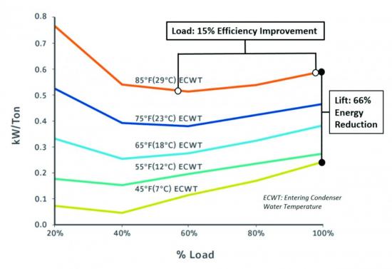
Chiller efficiency vs. load and lift.
Best Practices: How does this help with heat pump performance?
Rob Tanner: Mother Nature doesn’t provide design wet-bulb conditions every hour of the day. The below-design wet bulb temperatures are great for cooling-only with 95°F (35°C) or less condensing temperatures. When you switch to heat recovery system designs, the 95°F (35°C) goes up to as much as 185°F (85°C) condensing conditions to meet the heat requirement temperatures.
Whatever people are asking for today, except at reduced load, you don’t get cooler condenser temperatures. You asked for 180°F (82°C). At 50% load, normally on a cooling-only chiller, I would see 85°F (29°C) in and 90°F (32°C) out, as opposed to 85°F (29°C) in and 95°F (35°C) out. In a heat recovery chiller, instead of 160°F (71°C) in and 180°F (82°C) out, I’m going to see 170°F (77°C) in and 180°F (82°C) out. So my 180°F (82°C) condenser out and my 44°F (7°C) evaporator out are constant, and we call that constant lift. My bell curve is now a flat line at the top of the bell. My lift never gets reduced in a heat recovery application. You can’t get as much turndown because your bell curve isn’t as wide at the top.
With improved technology, we’re trying to help that, but there’s an unfortunate limitation to the shape of the bell curve. It’s also a different use of lift: The lift never varies in a heat pump application, but in cooling-only, the lift is less than design 99.6% of the time. In a heat pump application, lift is never reduced, unless you take a heat pump chiller, and then, if it’s too much heating, you can convert to cooling-only applications. We see that as a lower lift application.
When you reduce design lift on a chiller, you have different compressors and impellers giving you different performance improvements with the reduction in lift. The other thing we’ve done with technology is creating the variable orifice. When we added the subcooler, we needed to maintain a liquid seal on the refrigerant metering device, which used to be a hole in a plate. If you lose your liquid seal, gas goes from the condenser right into the evaporator. If it doesn’t condense, it can’t boil in the evaporator because it’s already a gas. So, internal high gas bypass is an inefficient product design. If you put in a variable orifice, you can modulate the diameter of the opening so you always maintain your liquid seal, and then you always maintain your subcooler efficiency improvement as an effective part of your chiller efficiency. Again, you’re modulating things with extra control algorithms.
We’ve now moved to high-speed induction motors – a new technology – and high-speed permanent magnet rotor motors. With the use of a variable speed drive, we can convert 60 Hz AC power all the way up to 340 Hz. You’re thinking, "How do I get 340 Hz? The United States is a 60 Hz country." Well, that’s what the AC inverter variable speed drive does. Technologies allowed us to miniaturize the size of the variable speed drive. We liquid-cooled the variable speed drive close to 30 years ago. That technology allows us to shrink it and put it on a chiller, so I can give my motor a 187.5 Hz output.
Variable speed drives allow us to go to different motor designs, which allow us to get rid of gears. We’re adding this crazy concept of a high-speed permanent magnet rotor at a high, odd-sounding 340 Hz out of an inverter. There are still plenty of inverters that take 60 Hz in and give 60 Hz out. They also take 60 Hz in and give 49 Hz out. We’re redesigning the shape of the bell curve every time we change the speed of the motor. We’re making the bell curve flatter or taller. When you go to high-speed induction motors and high-speed permanent magnet motors, you’re running a whole other speed. From a motor horsepower standpoint, the higher the speed, the higher horsepower you can get out of it from a smaller shape.
About Johnson Controls
Johnson Controls’ mission is to reimagine the performance of buildings to serve people, places and the planet. Johnson Controls offers the world’s largest portfolio of building technology and software, as well as service solutions from some of the most trusted names in the industry. For more information, visit https://www.york.com.
For similar articles on Chiller Technology, please visit https://coolingbestpractices.com/technology/chillers.
Visit our Webinar Archives to listen to expert presentations on Chiller Technology at https://coolingbestpractices.com/magazine/webinars.