Selecting the optimal cooling temperature can lead to significant energy and water savings
Chilled water (CHW) systems are common in plants where process cooling is needed. These systems, which use refrigeration cycle machines to provide cool water commonly around 45-60°F (7-16°C), are vital to proper manufacturing facility operation. In many plants, the cooling equipment is one of the largest categories of energy use, which makes the efficiency of these systems critically important.
Depending on the process environmental requirements, CHW may also be used for air handlers providing spot cooling to workers or for complete room cooling. This may occur, for example, where dehumidification is needed to prevent plastic part molds from “sweating,” or condensing moisture from the air onto the molds which can result in off-spec parts.
However, many process cooling applications do not require the cool temperatures typically provided from CHW systems. One common application in plastics, printing and other processes is the use of “temperature control units” (TCUs), which are packaged devices with a pump, mixing valve and/or heat exchanger, and sometimes heaters to provide relatively precise temperature control of specific process loops at temperatures and/or pressures above the main cooling water supply system. TCUs are often set to temperatures well above the CHW supply temperature. Integrated Services Group has observed many systems running from 70°F up to 120°F (21 to 49°C) depending on the process and the specific application.
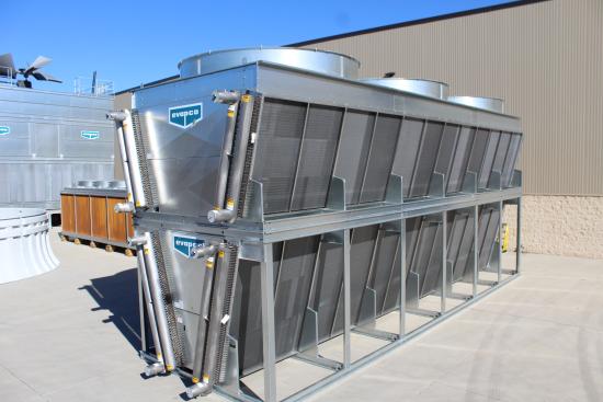
A dry fluid cooler.
This article will make plants aware of the energy and water use differential between CHW systems providing chilled water in a 45-60°F (7-16°C) range, and process cooling solutions at 70°F up to 120°F (21 to 49°C). The article will examine cooling resource evaluation criteria and supply water temperature specifications, then describe and compare process cooling options.
A Note on Glycol Systems
This article will refer to water as the cooling systems’ working fluid. Depending on geographic location (i.e. freeze risk) and working temperatures, some cooling systems use glycol blends rather than plain water. The concepts presented here apply equally to glycol systems although some adjustment in terms of potential approach temperatures and the cost of heat exchangers may be needed in the various details to account for the distinctions between glycol blends and pure water. One key point: Glycol can’t be used directly in any open-loop cooling tower systems.
Cooling Resource Evaluation Criteria
When process cooling is required, there are two primary factors that typically influence the choice of cooling method used:
- Basic adequacy of the cooling approach: Does it cool the process?
- Cost of the cooling approach: How much will it cost?
There are multiple facets to each of these, some of which are widely and routinely recognized and some of which are not.
Adequacy of the Cooling Approach
A given cooling approach is typically considered satisfactory if it meets the machine manufacturer’s stated cooling requirements or other plant owner-developed cooling parameters. These are commonly understood and evaluated in the following terms:
- Supply temperature: Will it meet the stated supply temperature?
- Supply pressure: Will it meet the required supply pressure?
- Cooling flow: Is the system capable of providing the required flow?
Somewhat less frequently considered, but nevertheless critically important, are the following:
- Stability/Precision: Can the cooling system provide the required temperatures and pressures at sufficiently precise and stable conditions?
- Reliability: Is the proposed design reliable in terms of redundancy and operation for minimal failures?
First Costs and Operating Costs of the Cooling Approach
Cooling system costs are most often evaluated like many other industrial systems where first cost is virtually paramount. More foresighted industrial systems operators will also consider the following:
- Energy operating costs
- Maintenance costs for routine service to equipment
- Other associated operating costs such as chemical water treatment, replacement filter media and water consumption
- Repair costs such as replacing heat exchangers scaled with minerals
- Capital costs for periodic renovation and/or replacement of major system components
These operating cost items are important because they can become substantial cost penalties to plants. Given the long life of process cooling systems, in many cases 20 to 30 years or more, choosing a system purely on lowest first cost can be expensive. Poor decisions here can burden a business with higher operating costs for many years.
What Process Cooling Supply Temperature Is Really Required?
As noted above, supply temperature is the first and foremost process cooling condition that must be satisfied. However, there may be alternatives capable of providing entirely satisfactory cooling with warmer temperature water. These may be accomplished by flowing more gallons per minute (GPM) through the process, using larger heat exchangers or combinations of these or other methods.
The critical question is what is the required temperature on the process side? If a machine requires 120°F (49°C) oil supply to a gear box, it can be provided with a non-CHW resource, even if the manufacturer specified CHW for the cooling function. As noted previously, this may require changing the heat exchanger and increasing the GPM. In any case, it must be done carefully and intentionally.
Process Cooling Alternatives
The following table lists process cooling water options as well as the reference CHW methods (water- and air-cooled systems). The alternatives are listed based on design conditions: what the specific technique would be capable of providing on a year-round basis, assuming the system is in good working order (reasonably clean heat exchangers, adequate pump flows).
To provide the most options for energy efficiency, some of the approaches are also listed with seasonal application opportunities and the available hour range for typical locations where they could be considered. These are listed as “Seasonal” applications rather than “Design” for the year-round usages.
Cooling Methods Sorted by Supply Temperature (High to Low)
|
Approach |
Time Frame |
Typical Supply |
System Average kW/Ton† |
Ann. Avg. GPM Per 100 Tons |
Appx Inst. Cost Per Ton* |
|
Dry Cooling |
Design @ 95°F (35°C) dry bulb |
105-115°F (41-46°C) |
0.25-0.3 |
0 |
$600-700 |
|
Adiabatic |
Design @ 78°F (26°C) wet bulb |
95-105°F (35-41°C) |
0.3-0.35 |
0.3-0.5 |
$700-900 |
|
Dry Cooling or Adiabatic |
Seasonal 3,000-5,000 hrs/yr |
70-95°F (21-35°C) |
0.2-0.3 |
0 |
$600-700 DC $700-900 Adiabatic. |
|
Closed-Loop Fluid Cooler Cooling Tower |
Design |
87-88°F (31°C) |
0.15-0.3 |
2.9 |
$400-500 |
|
Closed-Loop Fluid Cooler Cooling Tower |
Seasonal 3,000-5,500 hrs/yr |
55-75°F (13-24°C) |
0.15-0.3 |
2.9 |
$400-500 |
|
Open-Loop Cooling Tower |
Design |
85°F (29°C) |
0.1-0.25 |
2.8 |
$300-400 |
|
Free Cooling from Open-Loop Cooling Tower |
Seasonal 2,500-4,500 hrs/yr |
40 - 60°F (4-16°C) |
0.15-0.3 |
2.9 |
$1,100-1,300 |
|
CHW: Air-Cooled Chiller |
Design |
40-60°F (4-16°C) |
0.9-1.2 |
0 |
$1,200-1,500 |
|
CHW: Water-Cooled Chiller |
Design |
40-60°F (4-16°C) |
0.7-1.0 |
3.4 |
$1,000-1,200 |
†Tons in this table are refrigeration tons of 12,000 BTUs per hour removed from the heat load. Tower loads for CHW systems include the chiller refrigerant compressor heat rejection and may be expressed in other situations in 15,000 BTU per hour tower tons.
*Cost per ton for cooling system equipment and installation only. Does not include building and space costs, distribution piping or drops to equipment.
In addition to the tabular data, efficiency, water consumption and design supply temperatures are presented graphically in two charts. This makes it easier to relate the supply temperature and water consumption of the different options to their respective energy efficiency.
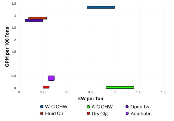
Cooling method efficiency and water use.
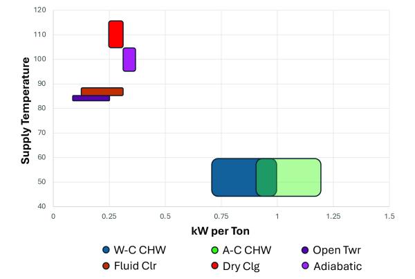
Cooling method efficiency and design supply temperature.
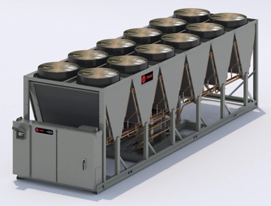
Air-cooled chillers provide chilled water with minimal water use, but at moderately higher energy cost.
Chilled Water Cooling
Chilled water is the default cooling system in many cases due to its ability to meet essentially all the cooling requirements in a plant, whether directly or via supplemental conditioning through TCUs. (Note: This article does not address low temperature applications such as ice tank thermal storage or other below-freezing cooling requirements.) In many plants, there is only a single distribution piping system and in such cases the water temperature must meet all cooling needs.
Chilled water can be supplied by either air- or water-cooled chillers with the resulting energy and water consumption shown in the accompanying table. The selection of one or the other depends heavily on energy and water costs and availability.
Air-cooled systems are often advantageous in smaller systems due to their simplicity (no open cooling towers, low water consumption, fewer system components) while water-cooled systems become compelling in larger systems where energy savings are significant and capital costs benefit from scale economies. This is especially true in cases where cooling towers are already planned due to air compressor or other machine cooling requirements.
The selection between air- and water-cooled chillers was covered as part of the November 9, 2023, webinar “Chiller Selections for Central Plants: Lowest Overall Costs for Process Cooling,” which is available on the webinar archives page of the Chiller & Cooling Best Practices website.
Free Cooling Chilled Water
Refrigerant cycle-based CHW is essential for year-round “design” process cooling requiring cooler temperatures. However, CHW can be provided for many hours a year at significant savings from cooling tower systems. By definition, this is a seasonal approach, which is not capable of providing design conditions throughout the year. Nevertheless, the high efficiency makes it an attractive supplement to systems already including cooling towers.
Typically, these are implemented through carefully sized plate heat exchangers to provide both loop isolation (so the “dirty” tower water is not mixed with the “clean” closed-loop CHW) as well as close approach temperatures between the leaving CHW and the entering tower water (usually 2-3°F or 1.1-1.7°C). This maximizes system operating hours for the greatest benefit from the investment.
Open-Loop Cooling Tower
Cooling towers are direct contact heat exchangers enabling the closest possible approach between the cooling water temperature and the ambient wet bulb temperature. For much of North America, the ASHRAE design wet bulb temperature is 78°F (26°C) with a common leaving water temperature target of 85°F (29°C). This just so happens to be the AHRI standard design entering condenser water temperature for water-cooled chillers (what a coincidence!). This 7°F (3.9°C) approach temperature difference (85-78°F; 29-26°C) can be reduced by selecting larger cooling towers, but it is difficult to cost-effectively get below 4-5°F (2.2-2.8°C) as the tower size becomes exponentially larger at narrower temperature differences.
In addition to chiller condenser cooling, open-loop cooling tower water is frequently used for air compressor cooling, hydraulic system cooling and other machine cooling applications. For the provided temperatures, open-loop cooling is relatively inexpensive and efficient, at least from the cooling system-only perspective.
Closed-Loop Cooling Tower
One of the drawbacks to open-loop cooling tower cooling is the condition of the water in the open air, direct contact system. Open-loop water typically has significantly higher relative mineral content due to the unavoidable mineral concentration from evaporation and tightly controlled blowdown resulting from efforts to minimize water use. In addition, open-loop water has contaminants picked up from the air flow through the towers, as well as entrained air and dissolved oxygen. Finally, the water must also have chemical or other treatment to minimize the effects in the plant of the various undesirable characteristics.
These characteristics often lead to oxidation corrosion in the piping system and components, mineral scaling in heat exchangers (particularly common in air compressors and hydraulics running at much higher temperatures than the typical chiller condenser) and transfer of ferrous corrosion products to other surfaces which might not otherwise have been affected, such as the tubes in chiller condensers, brass fittings and valves.
One method of eliminating the drawbacks to open cooling tower water is isolating the machine cooling from the open loop. This can be done through either a heat exchanger separate from the cooling towers (either a plate heat exchanger or a shell and tube) or through the use of a “fluid cooler” cooling tower design incorporating a closed-loop liquid cooling capability into the cooling tower itself as a pre-packaged unit.
The separate heat exchanger can provide a closer approach temperature to the tower water with 2-3°F (1.1-1.7°C) typical (similar to the free cooling approach). However, this design requires the additional space and equipment cost of heat exchangers and pumps (including any redundant units). Packaged fluid coolers typically offer water approach temperatures of around 5°F (2.8°C) and cost more than a standard open cooling tower, but are less costly than the total equipment cost of the separate heat exchanger design and require less space. As with many things, there are pros and cons to both methods.
Typical design temperatures are 87-88°F (31°C) for the open tower and separate heat exchanger method, and around 90°F (32°C) with fluid coolers. Note that water consumption can be slightly higher with the fluid cooler approach than the open tower due to the marginally higher energy use – and subsequent heat rejection – of the fluid cooler design (this assumes intentional high efficiency design of the open-loop system heat exchanger[s], pumps and piping).
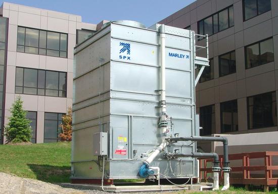
Fluid cooler cooling towers combine closed-loop cooling and evaporative heat rejection in a single, unified package.
Seasonal Closed-Loop Cooling Tower
While closed-loop cooling tower cooling can’t provide temperatures below the mid-80s° F (27°C) at design conditions, they can provide efficient lower temperatures on a seasonal basis.
Depending on the required temperature, where the higher the temperature the higher the hours and vice versa, this method can provide moderate temperature cooling water in the range of 55-75°F (13-24°C) at economical energy costs. Water consumption remains essentially unchanged from the other cooling tower-based methods.
This approach is distinguished from CHW free cooling only in the temperatures being provided. It is provided as an alternative for cases where separate CHW and tower water distribution piping systems are in place (more typical in larger plants) and where worthwhile numbers of TCUs are operating to supply moderate cooling water temperatures to processes that normally require CHW as a resource (i.e., below the mid-80s°F or 27°C). When seasonally offsetting CHW use, the benefits are as cost-effective as free cooling. Note that in many cases where this would apply, CHW free cooling would potentially provide greater savings by offsetting a greater cooling system load; however, in other situations, the CHW conditions or the specific local climate may make CHW free cooling too limited, raising the potential benefits of the higher seasonal closed-loop tower cooling option.
Reduced Water Consumption Cooling Methods
With the exception of the air-cooled chiller option, all of the preceding cooling methods have required the evaporation of water in a cooling tower as the final step in rejecting process heat to the environment. However, there are cooling methods that don’t require the same water consumption, particularly adiabatic cooling and dry cooling.
The trade-off with these methods is they only provide relatively warmer cooling water at the design conditions. Depending on the locational availability of water, and also the required cooling temperatures, these methods may be applicable for many machine cooling purposes.
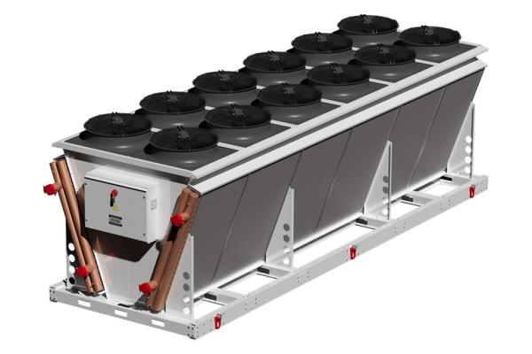
Dry cooling units provide cooling with no water consumption, although the available temperatures are higher than with other options.
Dry Cooling
Dry cooling systems are air coil-based systems in which the process cooling liquid is run through the coil tubing with ambient air passed through the coil and fins. An automobile radiator is a common example of dry cooling.
Because the only power consumption is by the fans (plus potentially some additional pumping energy from the coil liquid flow losses), dry cooling systems are the most energy efficient type of heat rejection. Significantly, the water consumption for these is zero as they do not use evaporation in the cooling process.
Historically, dry cooling systems have been relatively rare in general manufacturing cooling applications although they are widely applied in select industries with applicable temperatures for cooling hydraulic and gearbox oils and compressed gases. With current water availability concerns, cooling tower manufacturers are developing innovative new unit configurations to improve the performance of dry systems, for example, making stacked V systems offering more heat rejection capability in a smaller footprint than traditional horizontal or single V coil units.
Critically, the non-evaporative heat rejection aspect of dry cooling systems limits their ability to provide cooler temperatures compared to other cooling designs. Cost-effective systems are typically limited to supply temperatures around 10-20°F (5.6-11.1°C) warmer than the ambient cooling air. In practice this means design supply temperatures of 105-120°F (41-49°C) cooling water based on design ambient air temperature of 95 or 100°F (35 or 38°C). Closer approach temperatures (5-10°F or 2.8-5.6°C) can be obtained with larger coil systems relative to the heat rejection rate, and these may be desirable in locations with moderate peak dry bulb temperatures and significantly limited water availability. In these cases, the additional coil unit cost would be offset by the water savings.
Average cost per ton for dry cooling units selected for a typical 10-20°F (5.6-11.1°C) approach to design ambient air temperature is around $600-700 per ton. Depending on the coil tubing design, there may be incremental pump requirements (i.e. more horsepower due to higher head demands) which should be included in the relative system cost comparison with other system designs.
From an operations perspective, dusty or corrosive environments can be challenging due to coil plugging and fin and coil tube surface corrosion. Coil systems must be kept reasonably clean to perform as intended, as oxidation of the fins (typically aluminum) and/or the tubes (typically copper but sometimes stainless or galvanized steel) reduces the heat transfer performance of the coil. The lovely blue-green patina that gives character to copper statues and architectural features unfortunately consists of copper carbonate, which under ordinary circumstances can modestly reduce the heat transfer of the coil.
Most important to any coil-based system performing to its design rating is ensuring full air flow through the coil at the specified conditions. Off-design air flows can be low cfm (caused by coil blockage or fan failures) or above design entering air conditions due to air recirculation or induction of hot exhaust from other sources. Reduced air flow and/or warm entering air are typically more harmful than coil corrosion except in acute circumstances.
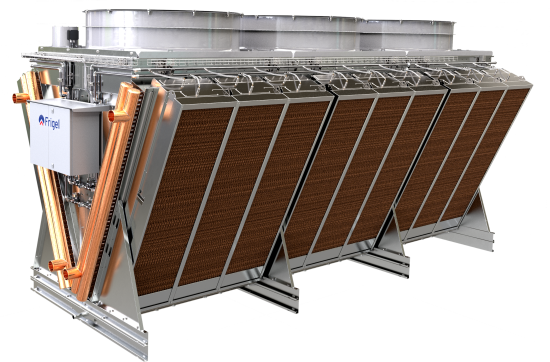
Adiabatic systems offer a balance of modestly cooler water temperatures with limited use of water at peak conditions.
Adiabatic Closed-Loop Cooling
Similar to dry cooling systems, adiabatic cooling systems are air coil-based systems. To improve their performance over conventional dry coil systems, adiabatic units are supplemented with evaporative pre-cooling of the incoming air, typically in the form of spray heads or wetted pads.
The evaporation of water in the air reduces the dry bulb temperature several degrees and improves the performance of the coil vs. the straight dry bulb air temperature otherwise entering the unit. Critically, the lower water temperature is often sufficient to support machine cooling applications that require maximum temperatures of 90-95° (32-35°C) at design conditions.
The coils themselves don’t perform any better than in plain dry-cooling applications. Instead, the lower entering air temperature enables the coils to supply modestly cooler water. The effect is nearly linear to the reduction in the dry bulb air temperature after the evaporation. Consequently, the relative benefits of adiabatic cooling systems would be significant in a hot, and/or dry climate (e.g. Phoenix, AZ, 110.2°F [43.4°C] dry bulb, 70.0°F [21.1°C] wet bulb [all data from ASHRAE 2005 0.4% design conditions] or Denver, CO, 91.2°F [32.9°C] dry bulb, 60.6°F [15.9°C ] wet bulb), while a more humid location such as New Orleans, LA (93.8°F [34.3°C] dry bulb, 78.8°F [26°C ] wet bulb), would see less meaningful differences.
Note that the entering air temperature is not lowered all the way to the wet bulb temperature. There is still an approach difference between the wet bulb and the actual entering air dry bulb post-humidification, typically 8-10°F (4.4-5.6°C). However, the nearly 30°F (16.7°C) difference between dry bulb and wet bulb in drier climates means water from the adiabatic coils can be significantly cooler than from the dry cooling units only.
Adiabatic systems at design conditions can typically deliver 90-100°F (32-38°C) cooling water depending on the unit selection. Cost is moderately higher than dry cooling units due to the additional complexity of the evaporative features (spray system or evaporative pads, circulation pumps, controls), with a typical range being from $700-900 per ton. In addition, there is the cost of water consumption when the evaporation systems are operating.
Similar to dry cooling coils, adiabatic system performance depends on good air flow at the required conditions. In addition, water quality must be considered for spray nozzle function and/or moisture pad scaling. Spray nozzles have less impact on air flow but can be prone to poor spray patterns or dripping from partially clogged nozzle openings, and both conditions reduce the effectiveness of the evaporative cooling. The ideal spray system completely evaporates the water spray without wetting the coils. Some systems direct the spray away from the coils to avoid this, but the coil intake air velocity has to be high enough to ensure the humidified air is pulled into the unit.
Wetted pads are somewhat less sensitive to water quality but can still have mineral scaling (which can restrict air flow) and channeling (which results in poor evaporative effect) if the water distribution system isn’t clean and working well. Moreover, the pads themselves can trap dirt and choke the coil air flow. Conversely, they can also protect the coils from fouling, which is beneficial if the pads are kept clean enough to not impact the air flow.
Generally, care must be used in choosing this design and establishing the maintenance protocol. If possible, dusty environments should be avoided and the systems either placed in less dusty locations or another cooling method should be used. As with dry cooling coils, reduced air flow can significantly impact system performance. This is more likely to deliver poor results if not closely managed. Periodic coil cleaning and regular replacement of the pads are best practices for operating these systems.
Selection Questions Summary
Reviewing the following questions will help clarify the applicable choices for cooling method in any particular situation:
- What is the required temperature for the cooling application?
- Can the temperature be raised by increasing cooling flow, e.g. using larger heat exchangers?
- Which is the more critical constraint: energy efficiency (high power cost location) or water consumption (water constrained location)?
- Is there already cooling equipment at the location? What type is it and is there available capacity, either year-round or seasonally?
- Does the potential exist to use a method seasonally if not applicable for design/year-round use?
- Is the cooling load large enough to make the seasonal use cost-effective in either energy or water savings?
- Are there environmental considerations (high levels of dust, space limitations) that could affect the reliable operation of the cooling system?
- Is the host site reasonably capable of operating the system given the staffing and operating capability of the plant?
As always, any decision is a compromise among many competing factors. In most production situations, reliability and operation simplicity (at least the aspects relevant to the plant operators) are the most critical factors in a successful solution.
Conclusion
Process cooling can be provided through a variety of means depending on multiple factors related to the application and location. This article reviewed various cooling methods typically available for industrial uses highlighting their efficiency, water use and operating implications.
Any decision on cooling method is a trade-off between multiple competing factors. In some situations, one factor (such as water use) becomes paramount in the choice. Many times, there are different options that could be satisfactory. In these cases, informed decisions balance the pros and cons of the alternate approaches and their demands on the plant. Company culture and corporate support are important factors, but these should not prevent users and engineers from implementing better solutions when the opportunity exists.
Images courtesy of EVAPCO, Frigel, Kaltra, Marley and SPX Technologies and Trane.
About the Author
Clayton Penhallegon, Jr.is President and Managing Member of Integrated Services Group, which specializes in industrial cooling water system operational effectiveness and cost reduction. He has worked for over 35 years with various industries including plastics, paper, wood products, metal containers and textiles. He holds a Bachelor of Mechanical Engineering from Georgia Tech, an MBA from Georgia State University and is a registered PE in Georgia.

Clayton Penhallegon, Jr.
About Integrated Services Group
Integrated Services Group performs industrial cooling water system operational effectiveness and cost reduction technical services. Its services include system assessments, new and upgrade system design, system start-up and retrocommissioning and high efficiency control design and implementation. ISG celebrated its 25th year anniversary in 2022 and serves clients throughout North America. For information, visit https://www.isg-energy.com.
For similar articles on Cooling Towers please visit https://coolingbestpractices.com/technology/cooling-towers.
Visit our Webinar Archives to listen to expert presentations on Cooling Technology at
https://coolingbestpractices.com/magazine/webinars.